Optimising Steel Structures with FEA
Reading Time: 6 minutes
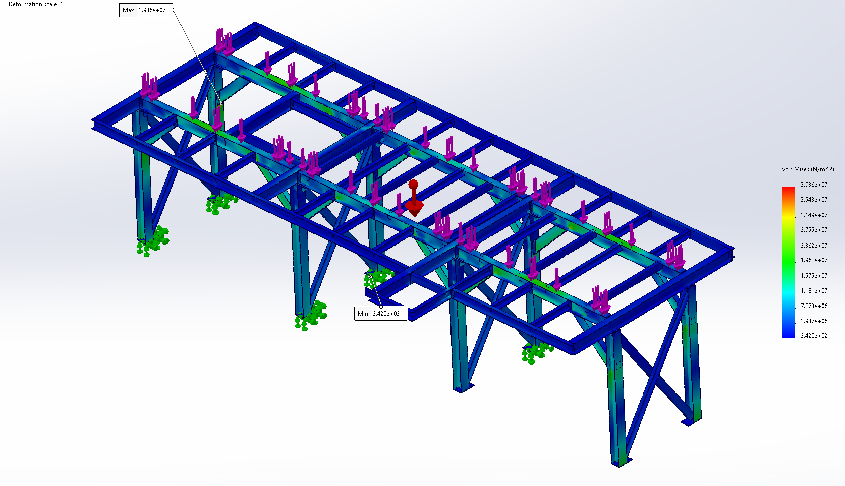
The quickest way to misuse FEA is to treat red as bad and blue as spare capacity. A stress plot can look authoritative even when the loads are incomplete or the supports bear little resemblance to the real structure. The solver will still return an answer. It has no way of knowing whether the engineering question was sensible.
Steelwork optimisation suffers when the analysis becomes a search for the lightest model that still runs. Sections are reduced until utilisation approaches a chosen limit, then the result is presented as efficient. That approach may create excessive movement or move the problem into buckling. It can also replace a simple member with a lighter fabrication that costs more to detail and build.
Useful optimisation starts with the load path and ends with a structure that can be manufactured. FEA sits between those decisions. It shows how a proposed arrangement behaves, allowing the engineer to change the right part of the design before committing to steel.
What optimisation means
Optimisation needs a defined target. Lower mass may matter where modules have to be lifted into a live plant, but weight is rarely the only measure of a good structure. Deflection can govern equipment support steelwork long before the material reaches its strength limit. On an access platform, stiffness may be needed to control movement under footfall or operating machinery.
The design basis must be settled before member sizes are adjusted. FEA can assess only the actions included in the model, so normal operation is one part of the duty. Maintenance may place a removed motor on the deck. Equipment loads can enter through small mounting areas, while an external frame may have a different governing case under wind. The combinations and performance criteria need to reflect when those conditions can occur together.
Efficiency also includes the route to manufacture. Repeated section sizes can simplify purchasing and reduce workshop errors. A standard section that is slightly heavier than the calculated minimum may be cheaper than a special order, particularly when the alternative needs extra connection work. Before optimisation begins, the engineer should know which outcome matters and how it will be measured. Without that definition, the process becomes trial and error.
Model assumptions
A global model should explain how force moves through the complete frame. Floor beams need a credible path into the main steelwork, while bracing should carry horizontal actions towards real supports. Reaction forces provide an early sense check. If they do not balance the applied load, or appear at supports that could not carry them in practice, there is little value in refining the member sizes.
Boundary conditions deserve particular suspicion because they can make a weak arrangement appear stiff. A nominally pinned joint still has some rotational stiffness, whereas a connection described as rigid may rotate because its end plate or supporting member is flexible. Baseplates and anchors influence how load enters the foundation. Fixing every support in all directions often suppresses the movement that the structure would experience on site.
The global model does not need every bolt and weld. It does need connection assumptions that match the details likely to be built. Where plate bending or local load introduction matters, a separate detailed model is usually clearer than filling the whole frame with solid elements. The local analysis can then answer a specific question without disguising the overall behaviour behind a large mesh.
Decks are another common source of false stiffness. Grating contributes little as a diaphragm unless the support and fixings have been designed for that action. Floor plate may contribute more, but only when the load transfer into the frame is credible. Treating every deck as perfectly rigid can shorten the apparent load path and make the frame look more stable than the fabricated structure.
Load path first
When a member appears heavily utilised, making it larger is the obvious response. It is not always the useful one. The beam may be attracting load because an adjacent bay lacks stiffness, or because the support arrangement forces bending into a member better suited to axial load. Strengthening that beam can add steel while preserving the inefficient behaviour.
Changing the arrangement often produces a better result. Moving a support or adding bracing in the right place can reduce bending across several members. Where flexural stiffness is still needed, increasing beam depth may use material more effectively than adding the same mass elsewhere in the section. These changes alter how the structure works rather than merely increasing its resistance.
Low utilisation also needs interpretation. A member may have been selected to match the depth of surrounding steel or to leave enough room for a practical connection. It could be controlling vibration despite carrying modest static stress. Removing that apparent surplus may save little weight once stiffeners and more difficult joints are added. FEA helps compare alternatives, but section availability and fabrication effort still decide whether the numerical optimum is worth building.
Stability belongs in the same conversation. Slender steel members can reach a buckling limit before the material yields, so a calm stress plot does not prove that the arrangement is safe. Beams need realistic lateral restraint and compression members need an appropriate effective length. Thin plates may introduce local modes that a simple beam model cannot represent. Optimisation should remove unused material without removing the conditions that keep the structure stable.
Consider more than just stress
Stress is one result among several. An optimisation review becomes more useful when each output is tied to an engineering question rather than treated as another image for the report.
| Result | Consider |
|---|---|
| Reactions | Do the loads reach credible supports and remain in equilibrium? |
| Displacement | Will movement affect use, alignment or connected equipment? |
| Member forces | Which parts of the frame carry the governing actions? |
| Mode shapes | Where could instability or dynamic response develop? |
| Local stress | Is the peak physical, or created by modelling detail? |
A structure can remain below its stress limit and still be unsuitable. Deflection may disturb the alignment of supported machinery. An access platform can also feel unstable even where strength is adequate. The displacement result is meaningful only when the model represents the stiffness of the supports and the connections along the load path.
Vibration may require its own assessment. A natural frequency close to the operating speed of machinery can produce an unacceptable response under a small repeating force. Adding mass is an unreliable default because it can move the frequency in the wrong direction. A change in stiffness or support position may solve the problem with less structural disruption.
Buckling output also needs care. An eigenvalue analysis is useful for revealing likely modes and showing where the structure is sensitive, but it is based on an idealised geometry. Real steelwork is imperfect and contains residual stress. Its connections rarely behave as perfect mathematical restraints either. The eigenvalue should not be lifted from the software and labelled as a factor of safety. Code-based member checks or a nonlinear analysis with suitable imperfections may be required, depending on the limit state.
Highly localised stress peaks deserve the same restraint. A sharp re-entrant corner or point constraint can create a result that keeps rising as the mesh is refined. That does not automatically indicate a physical failure. It may show that the model idealisation is singular, or that the result needs to be assessed over a meaningful structural region. Mesh density cannot correct a poor representation of load introduction.
A defensible result
An FEA result becomes useful when another engineer can understand why it should be trusted. Start by proving that applied loads and reactions balance. Then inspect the deflected shape and compare the response with an expected order of magnitude. Hand calculations remain valuable here. They expose a misplaced restraint or unit error faster than a polished contour plot.
Numerical sensitivity must also be demonstrated where it affects the conclusion. NAFEMS guidance on mesh convergence explains why the result should not change materially as the mesh is refined. Convergence does not mean making the entire model uniformly fine. It means identifying the output that matters, refining the relevant region and showing that the design decision is no longer controlled by element size.
The analysis still sits within the structural design method. Member and connection resistance need assessment against the standards defined for the project, while serviceability follows its agreed criteria. BS EN 1993-1-14:2025 now provides specific rules for steel design assisted by FEA. The project specification should state the applicable Eurocode generation and any relevant National Annexes rather than relying on the software settings.
Documentation should explain the model, not bury it under screenshots. The calculation record needs to make the load cases and principal assumptions clear, then identify the criteria that governed the final arrangement. Limitations matter too. If a connection has been idealised or a dynamic effect assessed elsewhere, the reader should not have to infer that from the mesh.
The released design must match the analysed one. A support moved in CAD after the final run can change the load path, while a substituted section may alter stiffness enough to affect serviceability. Fabrication and installation conditions also need carrying into the model where they govern. The link between analysis and fabrication drawings is part of the calculation, not an administrative task after it.
At ATLUS, simulation and analysis is used to develop steelwork while the arrangement can still change. We use FEA to understand the load path and test structural alternatives, then verify the chosen design against its real duty and fabrication strategy. If you need to reduce weight or resolve poor structural performance, talk to us about the engineering problem.