Fabrication Drawings: Best Practices for Steelwork
Reading Time: 6 minutes
A finished 3D model can make a steel structure appear complete. Every member is in position, the connections look resolved and the overall arrangement is easy to understand. That creates a dangerous sense that the documentation is nearly finished. In practice, the model has answered only part of the question.
The workshop needs more.
Fabrication drawings turn the engineering design into controlled manufacturing information. They define what must be made and how the parts relate, with the acceptance requirements made explicit. When information is missing, the fabricator has to ask. When it conflicts, somebody has to decide which version to trust, often after material has been cut. A good drawing package removes those decisions without trying to dictate every detail of the fabricator's method.
One design record
Every project should define its controlling design record. That may be the issued drawings, an approved 3D model or a stated combination of both. The choice matters less than the control around it. If a dimension changes on a drawing while the model remains untouched, two versions of the component now exist. The same problem appears when revised model geometry does not reach the PDF issued to the workshop.
Derived files need equal care. DXFs and NC data are convenient because they can move geometry directly into production, but that efficiency magnifies any error in the source. Each file should carry a clear relationship to the approved model or drawing revision. Informal exports should never sit beside released manufacturing data with no indication of status. The workshop should be able to identify the current definition without comparing files or relying on filenames such as “final” and “final revised”.
BS 8888:2025 provides the UK framework for technical product documentation and specification, including information communicated through 2D drawings and 3D models. The applicable standard and edition should be stated in the project requirements. More importantly, the document-control process must make the approved information unmistakable. A well-drawn component can still be manufactured incorrectly if the wrong revision reaches the machine.
Fabrication model
A model intended for presentation can hide details that matter in production. A fabrication model should contain the sections and plate thicknesses that will actually be purchased, with individual parts kept identifiable rather than merged into a convenient geometric body. Holes need their real diameters and clearances. Copes must account for section radii, while folded parts need bend radii that suit the material and proposed process.
Connections also need to be checked as work, not geometry. A bolt may fit in the finished model but be impossible to insert once the surrounding members are assembled. A weld can be perfectly visible on screen while the real joint leaves no room for the torch. Tool access and hand clearance should be reviewed before drawings are issued, along with a credible assembly sequence. If the connection can only be built by passing one part through steelwork already in place, the model describes an outcome rather than a method of reaching it.
This is where design for manufacture earns its place. The point is not to model every workshop operation. It is to expose the decisions that determine whether the steelwork can be manufactured and assembled as intended. Our approach to design for manufacture treats those constraints as part of the engineering design, not a drawing-office check at the end.
Give each drawing a defined purpose
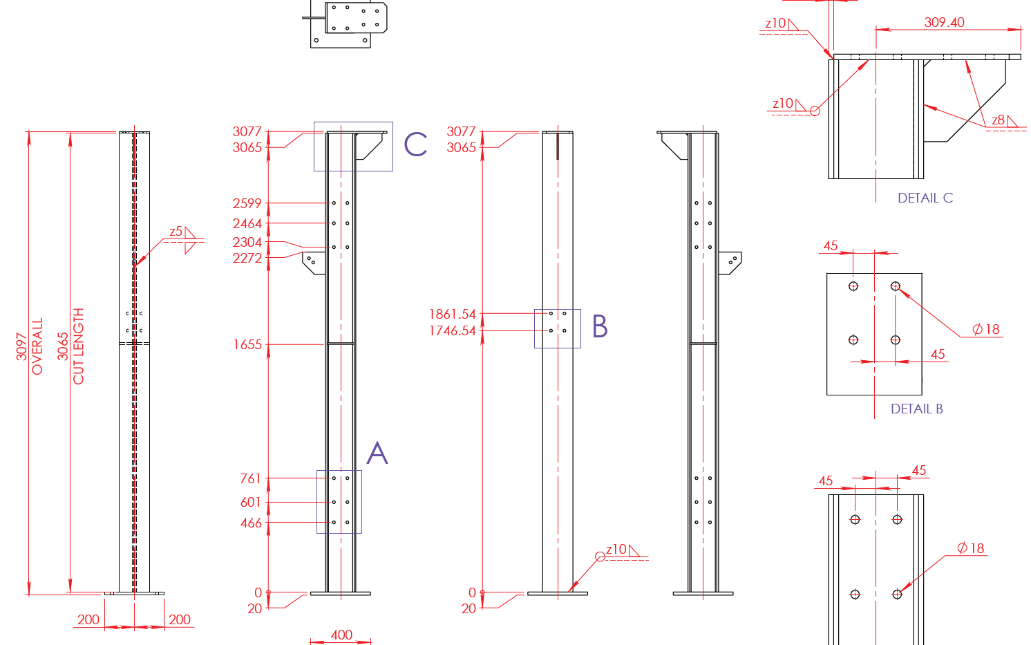
Each drawing in the package should have a defined job. General arrangements establish the structure against project grids and levels, with the site datums made clear. Assembly drawings explain how marked parts form a transportable or installable unit. Single-part drawings carry the information needed to make an individual plate or member, while the parts list supports material control and production planning.
These documents should complement one another without repeating every dimension. Duplication looks helpful until the same value appears differently on two sheets. Put information where it will be used and give each requirement one clear home. A principal level belongs on the general arrangement; the size and location of a hole group belong with the part being manufactured. Reference dimensions can help the reader, but they should be identified so that they cannot compete with the dimensions controlling manufacture.
Drawings also sit within a wider specification. For structural steelwork, the execution specification establishes requirements that do not belong on every sheet, including the applicable standards and inspection regime. The National Structural Steelwork Specification provides an established route for many UK building projects, but project-specific requirements still have to be defined. A drawing should communicate the design clearly, not become a crowded substitute for the rest of the contract information.
Dimension from stable datums
Dimensions should reflect how the component will be made and inspected. Hole groups are usually clearer when located from a common datum rather than chained from one feature to the next, where individual variations can accumulate along the part. The best datum is generally tied to function. Machinery mounting holes may relate to a centreline, whereas a baseplate could be set from the grid intersection used on site.
Overall dimensions remain useful as checks, provided they do not conflict with the dimensions controlling manufacture. Calculated dimensions should not be repeated simply because the CAD system can display them. Repetition can over-constrain the drawing or imply a tolerance the designer never considered. ISO 129-5:2018 covers dimensioning for structural metalwork made mainly from plates, bars and profile sections. The practical test is simple: the workshop should never need to scale a PDF or calculate a critical position from unrelated values.
Tolerances need the same discipline. Every fabricated component will vary from nominal geometry, especially after welding. Tight control belongs on features that govern fit or performance; applying it everywhere increases fabrication and inspection effort without improving the structure. BS EN ISO 13920:2023 provides general tolerance classes for welded constructions based on customary workshop accuracy and functional requirements. The selected class must suit the work, and any critical feature should receive an explicit limit.
Use complete material specifications
Descriptions such as “steel plate” or “mild steel” are not manufacturing specifications. Every part needs a material grade and complete size designation. Plates require thickness, while rolled sections need the exact section reference. Where impact properties, through-thickness quality or a particular product standard affect the design, they must be stated rather than left for procurement to infer.
The parts list, model and drawings must agree on item marks and quantities. Fasteners need more than a nominal diameter because the grade and product standard can change capacity, while the coating may affect installation. Surface treatment should identify which components are painted or galvanised, along with any areas that must remain untreated. Masking requirements are easy to overlook in CAD and expensive to recover after coating. For steelwork within its scope, BS EN 1090-2:2018+A1:2024 covers execution requirements that include constituent products, welding, geometrical tolerances, surface treatment and inspection.
Weld information should be complete without covering the drawing in repetitive notes. Location and required size must be clear, as should the distinction between workshop and site welds. ISO 2553:2019 defines rules for the symbolic representation of welded joints on technical drawings, with two recognised systems for identifying the arrow side and other side. Whichever system the project adopts must be used consistently.
Symbols do not remove the need for engineering judgement. A blanket instruction to weld every joint continuously can add heat and distortion, increasing cost without improving the connection. An underspecified weld pushes a structural decision into the workshop. The drawing should define the required result, leaving the welding sequence and other production choices with the fabricator where the specification permits. That division respects both design responsibility and workshop expertise.
Transport and erection
Fabrication drawings should describe assemblies that can leave the workshop and reach their final position. Module size has to suit the available transport, while weight and centre of gravity affect the lifting plan. Site access may force a large frame to be split in a different place from the most convenient workshop joint. That decision should be made while connections can still be designed around it.
Installation sequence affects the details too. Bolts need to remain accessible after adjacent modules are placed, and site welds require a workable position with suitable protection from surrounding operations. Temporary lifting points or bracing should be engineered for their real loads. Galvanised hollow sections need correctly arranged vent and drain holes, while external details should avoid water traps in service. Erection marks and orientation details are valuable where similar-looking assemblies could be turned or swapped.
The general arrangement and fabrication details should tell the same installation story. If the structure only works once everything is in its final position, the design has ignored the most difficult part of the job. Steelwork has to leave the workshop and reach its location before the final connections can be made.
Revision control
A technically correct drawing can still cause an error when its status is unclear. Every sheet needs a drawing number and revision. Its issue purpose must distinguish information for review from information released for manufacture. Revision notes should explain what changed, with altered details made visible enough for the fabricator to assess work already completed. The model and every derived production file must move with the drawing. Reissuing the PDF while leaving an older DXF in circulation creates two definitions of the part.
Superseded information should be withdrawn through a controlled issue process. Email attachments and marked-up workshop copies cannot become an alternative record. Before release, the drawing review should confirm that:
Every component has a unique and consistent mark.
Materials and quantities agree across the package.
Manufacturing dimensions originate from suitable datums.
Weld requirements are complete and physically accessible.
Tolerances reflect fit and function.
Surface treatment and masking requirements are defined.
Interfaces with equipment or existing steelwork have been checked.
Assemblies can be fabricated, transported and installed.
Digital production files match the issued revision.
Superseded information has been withdrawn.
This review is more valuable than a final scan for missing dimensions. It tests whether the package works as manufacturing information and whether the workshop can proceed without reconstructing the design. Questions will still arise on complex work, but they should concern genuine production choices rather than missing engineering decisions.
At ATLUS, fabrication documentation is developed from the coordinated model used to resolve the engineering design. We review drawings against the proposed manufacturing method and installation sequence before release, keeping the information clear enough to use on the workshop floor. If you need support with a steelwork drawing package, talk to us about the project.