FEA in Machinery Design: Why it Matters
Reading Time: 6 minutes
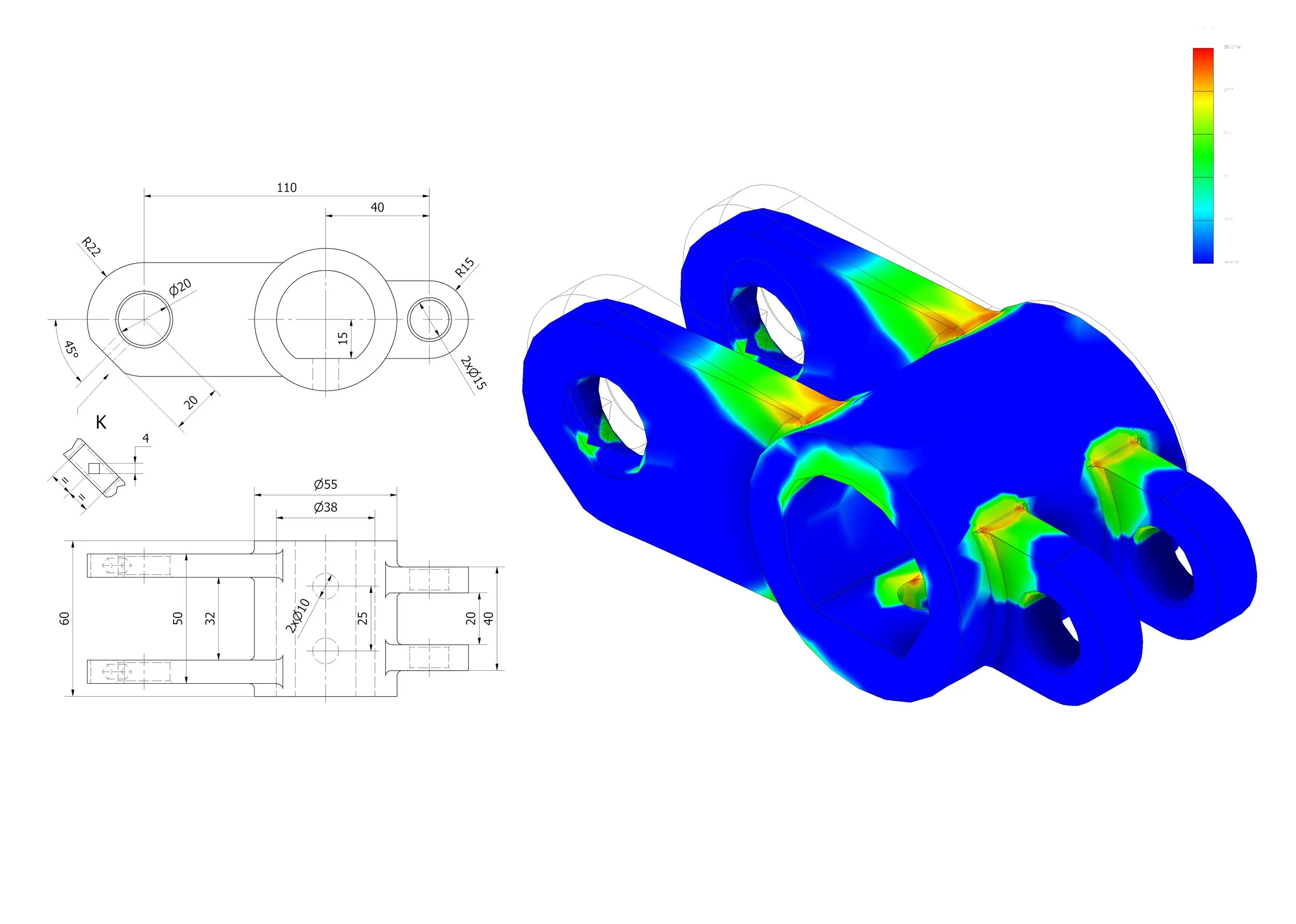
Modern analysis software makes it remarkably easy to produce a stress plot. Once the CAD model is imported, only a material and a few restraints stand between the user and the solve button. Within minutes, the screen is full of colour and the design appears to have been verified.
That apparent certainty is where the trouble starts. A machine frame can remain below yield and still move far enough to disturb a bearing alignment. A support arm may survive its normal load but fail after thousands of operating cycles. The model can also look stiff simply because the engineer fixed a surface that is flexible on the real machine.
None of these problems will be identified by asking whether the plot contains too much red. The useful questions are tied to machine behaviour: will the processing gap remain stable, and can the drive react a blockage load without pulling its supports out of alignment? Those questions must be settled before choosing an element size or adjusting the legend.
FEA earns its place when it helps the engineer understand that behaviour while the design can still change. It should expose assumptions and allow credible options to be compared before manufacture. Without those foundations, the same software gives an inaccurate answer a professional finish.
Begin with the machines intended function
Every analysis should begin with a decision. Perhaps the team needs to choose between two frame arrangements or confirm that shaft alignment will be maintained at a higher throughput. The required result follows from that decision. Stress may govern one component, while movement or fatigue life governs another.
Acceptance criteria should be agreed at the same point. A generic material yield limit says little about the displacement that a seal can tolerate or the angular misalignment permitted by a bearing arrangement. Where a recognised design standard applies, its checks and modelling requirements belong in the design basis. Project-specific limits should be written down too, particularly where equipment suppliers set tighter conditions than the supporting structure would otherwise require.
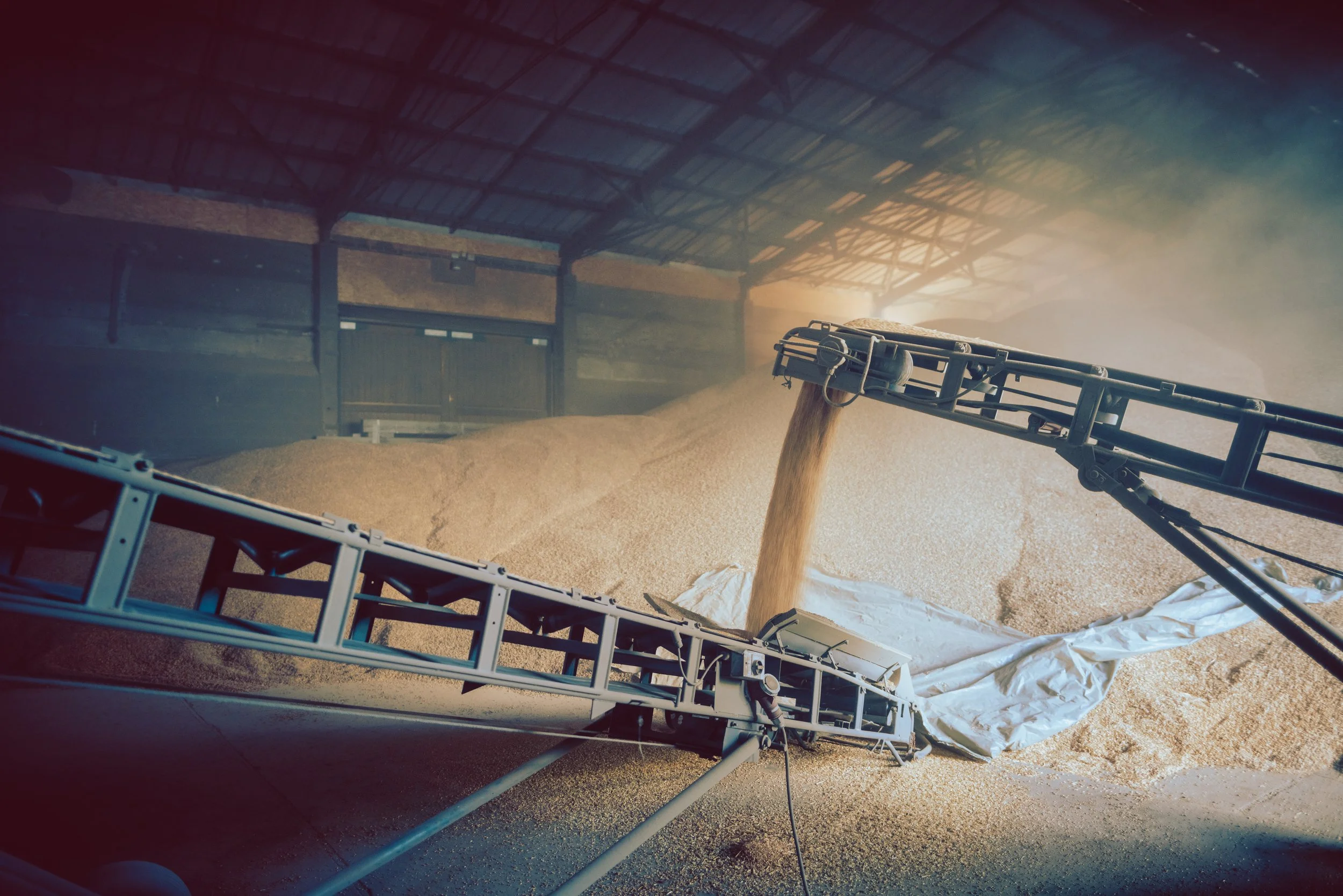
The loading then has to come from the real operating duty. On bulk-material or recycling machinery, a stated motor power is not a complete load definition. Feed size affects impact, while bulk density influences the working mass. Moisture changes how material moves through a chute, and an occasional oversize item may create a short event that is more demanding than steady production.
Normal operation is only the starting point. A loaded conveyor at start-up or a blocked screw at stall can place a different demand on its drive support than running at steady speed. The maximum available torque may enter the frame, provided the control system does not limit it first. Maintenance can change the load path again when a component is lifted or parked on a platform.
These cases should describe a credible operating envelope, not every load anyone can imagine. Applying all maximum values at once often produces a combination that cannot physically occur. At the other extreme, analysing only the cleanest production case ignores the events that commonly damage machinery. The engineer needs to understand the sequence of operation, the controls and the foreseeable misuse before deciding which combinations matter.
Frequency matters as much as magnitude. A high load that occurs once during proof testing is different from a smaller load repeated every few seconds for years. The machine specification should state expected output and operating hours, with significant cycles estimated where possible. Without that information, a fatigue calculation is built on guesswork regardless of how refined the mesh becomes.
This is why a useful machine specification is part of the analysis rather than a document that sits alongside it. It defines the boundary between normal duty and a credible extreme, then records any exclusions that need to be managed elsewhere. FEA can support the risk-reduction process described in ISO 12100, but it does not replace the wider assessment of hazards throughout the machine life cycle.
The load cases matter more than the colour plot
Loads do not act on an abstract frame. They enter through bearing housings, actuator pins, motor mounts and material contact. From there, force passes through fabricated joints and fixings before reaching the floor or an adjacent structure. If those interfaces are represented badly, the internal stress pattern can be wrong even when the applied load is correct.
Boundary conditions deserve more attention than they usually receive. Fixing every degree of freedom on a mounting face may be convenient, but it can create a support that is far stiffer than the real baseplate and anchors. A pin joint may carry shear while allowing rotation. A bolted flange can separate locally, changing both the contact pressure and the stiffness of the assembly.
The model should capture the behaviour that can influence the decision. That does not mean modelling every fastener or cosmetic fillet. For a complete machine, a beam or shell model may reveal the global load path more clearly than millions of solid elements. A local solid model can then investigate a critical bracket or contact region using forces taken from the global analysis.
Simplification still needs engineering judgement. Removing a small bracket is harmless if it carries no meaningful load, yet replacing a flexible connection with a rigid link can alter the response of the whole frame. Thin plates can contribute stiffness through membrane action, while access panels may contribute almost none once their real fastenings are considered. The test is whether the idealisation preserves the behaviour relevant to the question.
Movement is often the most useful result in machinery design. Consider two bearing housings mounted on opposite sides of a fabricated frame. Neither housing may show an alarming local stress, but differential movement between them can alter shaft alignment enough to shorten bearing life or disturb a coupling. Reading a single maximum-displacement value will miss that; the relative movement and rotation at the interfaces are what matter.
Local peaks also need interpretation. A point load or perfectly fixed sharp edge can create a mathematical singularity whose reported stress rises as the mesh is refined. The answer is not to accept the largest number on screen. The engineer must decide whether the peak represents a physical detail or an unsuitable idealisation, then whether a different assessment method is require
Failure over time
A static analysis is useful when the response is approximately linear and the load changes slowly. Many machines do not stay within that simple case. They may reverse under load and experience material impacts. Contact can open and close as the structure moves, while clearances allow components to take up load suddenly.
Some of these effects can be represented by an equivalent static load, provided the factor has a defensible basis. Others need a transient or nonlinear analysis because the load path itself changes during the event. Adding complexity by default is wasteful, but forcing every problem into a linear static model can hide the behaviour that governs the design. The method should follow the decision and the consequence of getting it wrong.
Fatigue deserves particular care around welded machinery. The maximum stress from one load case does not describe damage caused by repeated stress ranges. The weld category and direction of loading influence the appropriate fatigue assessment. A smooth contour through nominal plate stress cannot be read directly as a reliable fatigue life without a method suited to the detail and the applicable design rules.
Vibration introduces another form of service failure. A modal analysis can identify natural frequencies and show the associated mode shapes, but it does not by itself predict the operating response. Excitation at the machine operating speed and from intermittent impacts must be considered against those modes. If the frequencies are close, the next step may be a forced-response assessment or a measured vibration test rather than a thicker plate added by instinct.
Simulation is evidence, not proof by itself
A completed solver run is the start of the engineering review. First, applied loads and reactions should balance. The deformed shape should make physical sense, including its direction and relative scale. A hand calculation or simple free-body diagram can then test whether the model is returning the right order of magnitude.
Mesh refinement must be judged against the result that controls the decision. Global displacement may settle with a relatively coarse mesh, while a local stress needs finer elements and a suitable representation of the geometry. Uniformly reducing every element size creates a larger model without proving much. The useful evidence is that the relevant output no longer changes enough to alter the engineering conclusion.
Verification and validation address different weaknesses. Verification asks whether the numerical model has been solved correctly; validation asks whether the chosen model represents the physical problem well enough for its intended use. ASME V&V 10 provides a recognised framework for assessing the credibility of computational solid-mechanics models. A converged solution can still be invalid when the duty or support assumptions are wrong.
Existing equipment offers valuable validation evidence. Measured deflection or strain can be compared with the predicted response under a known condition. Maintenance records can reveal where cracks have initiated or fasteners repeatedly loosen. The model need not reproduce every imperfection, but a large disagreement should be investigated before it is used to approve a modified design.
The level of evidence should reflect the consequence of the decision. A simple bracket under a well-defined static load may need little more than a hand check supported by a small model. A high-cycle welded frame or safety-critical restraint requires a more rigorous route. FEA does not remove applicable code checks. It also sits within the risk assessment, with physical testing used where required.
Its greatest value often appears earlier, when several arrangements remain possible. A support can be moved before surrounding pipework is fixed. Frame depth can be adjusted without redrawing a released fabrication pack, and the effect of connection stiffness can be explored while the joint is still being developed. The analysis then guides the design instead of explaining a decision already made.
The final model must remain connected to what is built. If a plate thickness or foundation detail changes, the engineer should decide whether the analysis is still representative. That link continues through the design-for-manufacture review and into the released drawings. An approved report attached to an outdated CAD model is not useful assurance.
At ATLUS, simulation and analysis is used to answer defined machinery-design questions, then carry the result back into the working design. The objective is a machine whose real behaviour has been understood before steel is cut. If a new design needs verification or existing equipment is behaving in a way the drawings do not explain, talk to us about the problem.