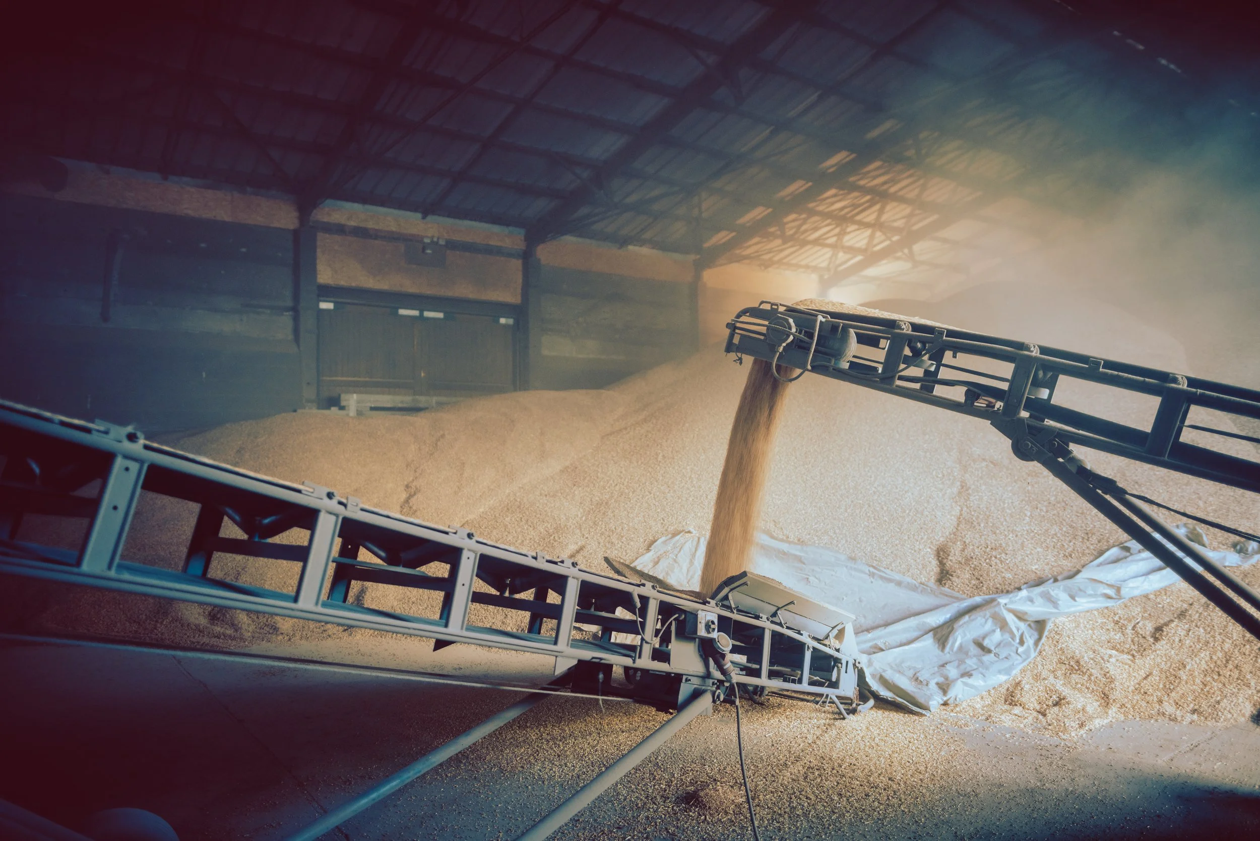
Conveyors: Improving Material Flow
Reading Time: 6 minutes
Spillage is often treated as a sealing failure. The usual response is to tighten the skirting or add more rubber around the loading zone. The conveyor may stay cleaner until the seal wears or the feed conditions change.
Reliable containment begins earlier in the flow path. The feed must arrive at a rate the conveyor can accept, and the chute must place it where the belt can carry it. Beneath the loading zone, the belt needs enough support to hold a predictable shape.
Skirting closes the controlled gap between fixed steelwork and a moving belt. It cannot correct a surging feed or poor trajectory, and it cannot follow sag between idlers. Extra pressure adds drag and wear without lasting improvement.
Treat the spilled material as evidence. Its location, timing, condition and associated feed pattern can reveal where control has been lost. Start there.
Finding the cause
Material found beneath a conveyor may have travelled along guarding or remained attached to the return belt before falling elsewhere. A useful inspection finds the first place where material leaves its intended path.
Observe it safely under representative operating conditions, then isolate it before close inspection. Record the material and feed condition when the loss occurred.
| Observation | Area to Investigate | First Check |
|---|---|---|
| Spillage around one side of the loading zone | Off-centre feed or uneven skirt contact | Material trajectory and belt position under load |
| Material falling from the carrying run | Excess volume or persistent mistracking | Peak feed condition and usable belt capacity |
| Deposits beneath the return belt | Carryback after discharge | Cleaner position, condition and discharge route |
| Loss after batch loading or with damp material | Feed surge or chute build-up | Upstream discharge pattern and internal chute condition |
Timing matters as much as location. A conveyor that spills after each loader bucket may be overloaded for several seconds, even when the hourly average looks acceptable. A problem limited to damp material points towards build-up or a change in sliding behaviour.
For persistent loss on one side, check whether the belt runs centrally when empty and moves after loading. That pattern often indicates an uneven stream. Random adjustments to training idlers can hide the symptom at one operating condition and make the conveyor less stable at another.
Design for peak volume
A conveyor can meet the required tonnes per hour on paper and still be overloaded in service. Mass flow says how much material passes in a given time; the belt carries the volume that mass occupies. A low-density product can fill the usable cross-section at a modest mass throughput, while moisture and particle shape change how the load settles.
Arrival rate matters too. A controlled feeder produces a predictable stream. Batch loading by grab or shovel may deliver a sharp peak followed by a quiet period, so designing from the average can hide the condition that causes the spillage.
ISO 5048 includes methods for determining conveyor capacity from the usable cross-section of a smooth belt. Belt width and troughing arrangement are part of that assessment, together with the load profile that can be carried without reaching the edge. Increasing belt speed should not be the automatic response to insufficient capacity. A faster belt can generate more dust and make the transfer harder to control.
Where the upstream process creates surges, a feeder or controlled discharge can reduce the peak without increasing nominal belt capacity. Define the material duty before changing hardware; Start with the Material: Defining Conveyor Duty explains the information needed for a sound design basis.
Present the material correctly
The incoming stream should meet the belt close to its centreline and travel in broadly the same direction. Off-centre loading increases pressure against one skirt while a gap opens beneath the other, and the uneven load can influence tracking beyond the transfer point.
A transverse stream has to turn after landing. Too little incoming velocity can form a pool before the belt accelerates the material; too much produces impact and uncontrolled movement. The chute should guide the stream towards the belt direction before contact, with horizontal velocity approaching belt speed where practical.
This principle appears in HSE guidance for mobile jaw crushers. It calls for maintained skirts and scrapers, along with central discharge into the feed hopper. Its scope is specific, though the loading principle applies more widely.
The chute controls the trajectory before material touches the belt. Large direction changes and excessive free fall disturb the stream and accelerate wear. Repeated impact can also produce more fines. Check the largest credible item as well as the normal flow, removing ledges or abrupt changes that can collect material. Liners belong in expected wear areas and must remain accessible for replacement.
Select wall angles from expected flow behaviour. Angle of repose describes how a material forms a pile, while wall friction and cohesive strength are more useful for difficult chute duties. Testing a representative sample is often more dependable than relying on a broad material description.
Discrete element modelling may help with complex trajectories, provided its inputs reflect the material. A detailed model built around guessed density or friction values creates false confidence.
Support the loading zone
A seal cannot follow a belt that continually changes shape. Sag between idlers opens gaps beneath the skirting. Increasing seal pressure may close part of the opening, though the extra contact raises friction and can score the belt.
The belt needs predictable support throughout the skirted area. Impact idlers or a suitable impact bed may be required where the stream lands, selected for the drop height and largest expected lump. Beyond that point, closer idler spacing or slider support can maintain a consistent belt line.
Material should reach the belt after it has formed its full trough. Loading over the transition from the tail pulley to the first fully troughed idler creates an unstable surface and reduces usable capacity where it is needed most.
Once the belt is stable, the seal has a consistent surface to work against and the material settles into a more controlled profile.
Set the skirting up to seal
Skirtboards define the loading zone and the flexible strip closes the gap above the moving belt. Incoming material should already be travelling within that boundary before it reaches the seal.
If the feed repeatedly strikes one skirtboard, correct the trajectory before fitting heavier wear material. Reinforcement may survive longer while the uneven stream moves the wear elsewhere.
The sealing strip should make light, consistent contact with the belt. Excessive pressure increases drag and can trap abrasive particles beneath the rubber. Keep adjustment points outside the guarded area and make wear parts replaceable without dismantling the chute.
The skirted section needs enough length for the load and displaced air to settle. Releasing material too soon allows fines to escape as the belt leaves the enclosure.
Dealing with carryback
Fine or damp particles may remain attached after the belt passes around the head pulley. This carryback falls beneath the return run or accumulates around rotating components, creating a separate maintenance problem.
A primary cleaner normally removes most of the adhering material. Some duties need a secondary cleaner. Blade material and mounting position must suit the belt surface and splice, with tension set to maintain the correct profile. Excessive pressure can shorten component life.
Removed material needs a clear route back into the process or an accessible collection point. A cleaner that discharges onto awkward steelwork has only relocated the cleaning job. A return plough can keep loose material away from the tail pulley.
Diagnose tracking under empty and loaded conditions. Movement that begins after loading usually points towards the incoming stream. Movement that persists when empty may come from pulley build-up, alignment, uneven tension, structural distortion or the splice. Correct the source before using tracking equipment to manage the remaining variation.
Controlling dust
Dust generation begins with material movement. A long drop entrains air, then impact at the receiving belt displaces more air from the enclosure. Fine particles follow that flow through gaps and openings.
Reducing drop height and guiding the stream smoothly onto the belt lowers dust at source. The enclosure needs enough volume and residence time for particles to settle. Extraction or suppression should be sized around the air moving through the transfer point; sealing every opening can pressurise the enclosure and force dust out elsewhere.
Material hazards must be understood before changes are made. Coal, wood, grain and certain metallic dusts can create a fire or explosion risk. HSE guidance on combustible dust covers frictional heating and other ignition sources in moving process equipment.
Conclusion
Introduce changes in a controlled sequence where the plant allows it. Replacing every suspect component at once hides which change produced the result. Keep inspection points safely accessible, and isolate and lock off the conveyor before removing a guard.
Spillage points to a loss of control somewhere in the flow path. The cause may sit in the feed pattern, material trajectory, belt support or cleaner arrangement. Finding it produces a better result than repeatedly adjusting the component nearest to the pile.
ATLUS develops transfer points as part of the complete conveyor system. We begin with the material duty and operating conditions, then develop changes around the constraints of the plant. Maintenance access and manufacture are considered before drawings are issued.
Learn more about our work in bulk-material processing and design engineering. If a troublesome transfer point needs a closer review, discuss the system with ATLUS.